![]()

"200Di" diesel conversion - how to do it
Developed
for Series Land Rovers by Glencoyne Engineering
![]()
![]()
![]()
![]()
![]()
![]()
![]()
![]()
![]()
(NOTE: following further development work on this conversion, I updated these notes on 13/10/07, 2/11/08, 18/4/09,10/1/11 and 4/7/11 to incorporate the latest modifications.)
This is not intended to be a comprehensive step by step instruction manual, but a guide which will help you with some of the trickier parts of the conversion. To attempt this conversion you need a reasonable degree of mechanical ability and some common sense. Working on old Land Rovers can be dangerous, especially if you use incorrect tools and unsafe working methods. Make sure you carry out your own assessment of the risks at every stage of the conversion, and take whatever steps are necessary to minimise those risks. I cannot carry out your risk assessment for you, and I cannot be held responsible if it all goes wrong and you end up in hospital or worse.
Before you start, you need to get hold of a Discovery 200TDi engine. Try to ensure that it comes with the following: starter, vacuum pump, lift pump, injection pump and injectors, alternator mounting bracket, inlet manifold, fuel filter assembly, heater plug timer and wiring, complete engine bay wiring loom (not essential but can be useful), battery cable and the pipe from the crankcase breather to the air filter. You do not need the power steering pump, the clutch or the air filter assembly and you will only need the alternator if you don't already have one. You will only need the turbo and manifold if you are planning to do a 200Di conversion as an interim step towards a TDi. 200TDi engines less turbo and manifold can sometimes be picked up very cheaply.
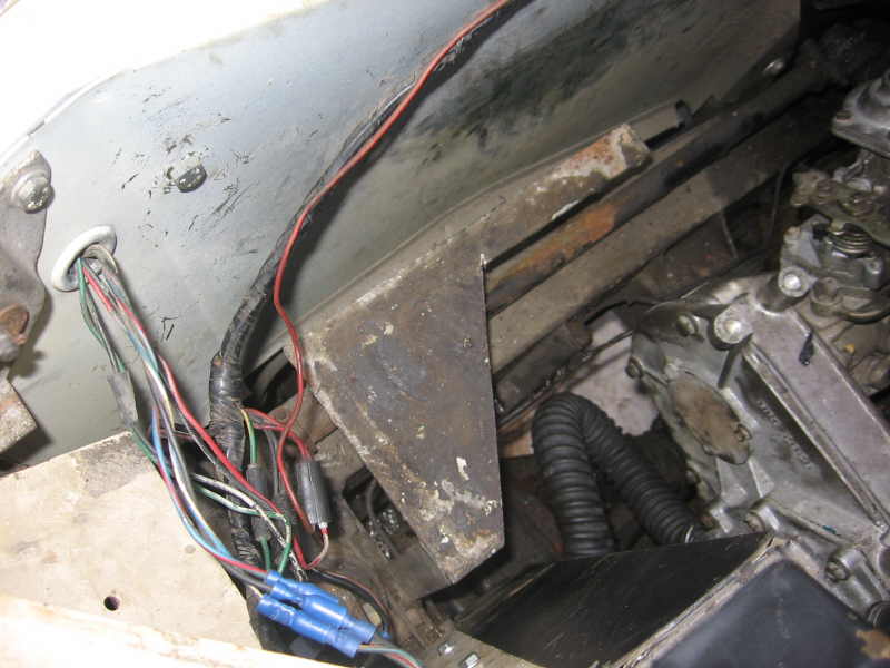
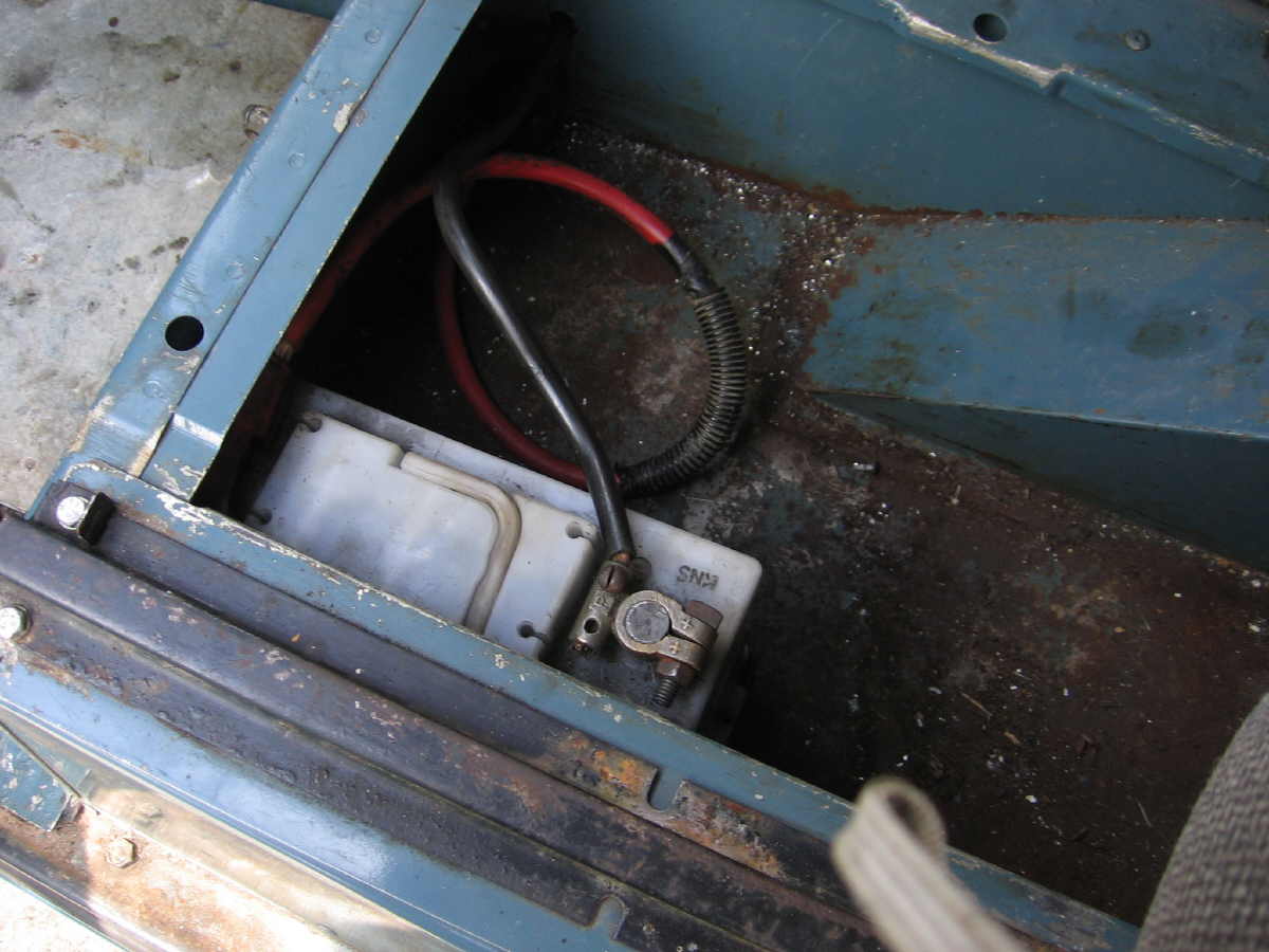
So, the first stage is to remove the battery, drain the cooling system and then remove the old engine as per the workshop manual. Once the engine bay is nice and clear, remove the air cleaner bracket and then cut back the battery tray as in the photo below, removing the support leg which goes onto the engine mount. The battery will be relocated under the passenger seat.
Now you need to turn your attention to preparing the engine. Firstly you need to strip any un-needed ancillaries - cooling fan, power steering pump, alternator, engine mounting brackets (keep the four large bolts to fit the new engine mounts), clutch and manifolds. Remove the turbo and exhaust manifold as one unit - there is a support bracket under the manifold which bolts to a bracket on the block, and also two oil lines (feed and return) from the turbo to the engine block which need to be undone before the turbo can be removed.
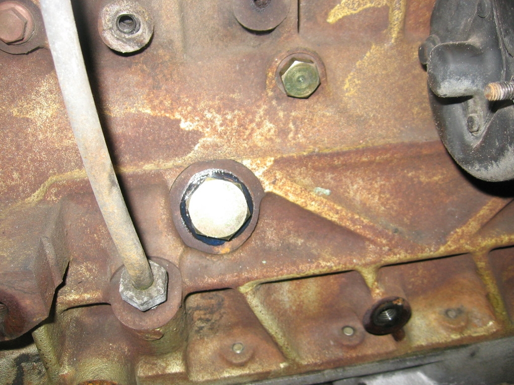
The turbo oil feed and return lines need to be blanked off. Your Land Rover dealer can supply suitable blanking plugs to replace the turbo pipe connectors. Part numbers are ETC5577 for the feed (with a suitable copper washer) and ETC8362 for the return. Alternatively, if you have access to welding equipment you can just unscrew the pipe connectors from the block, weld a bolt inside the end to seal them, then refit them.
Round the other side of the engine, the oil filter housing has connections for an oil cooler. We don't need that, so the filter housing has to be converted to 2.5 non-turbo spec. There are two different types of oil filter housing fitted to 200TDi engines, identifiable by the connections for the oil cooler types. The first (early) type has rounded ends to the pipes, the second has a flange and O ring to make the seal. The changeover took place at engine number 12L51183A, at the start of the 1993 model year. So most Disco engines will have the earlier type of filter housing.
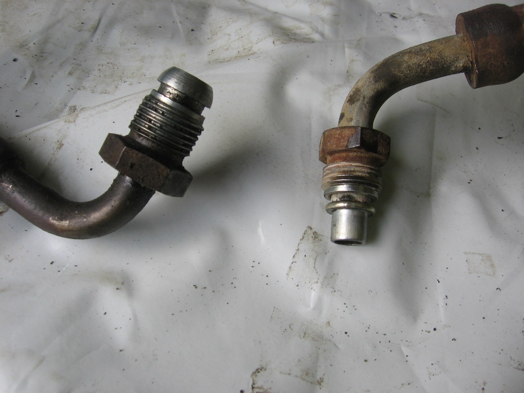
Early type on left, late type on right
It is simple to blank off the oil cooler ports. Undo the two bolts in the end plate, withdraw the plate and remove the thermostat and spring. Refit the plate with a new 'O' ring (use the correct Land Rover part ERC5913 or you will have problems with oil leaks), and then blank off the oil cooler connections. On early type housings you will need two blanking plugs (part number RTC6851) and copper sealing washers 213961L. Later type housings have smaller ports threaded M20x1.5. If you have a hunt around on the Web you should be able to find a hydraulic or plumbing supplies company that can supply plugs this size.
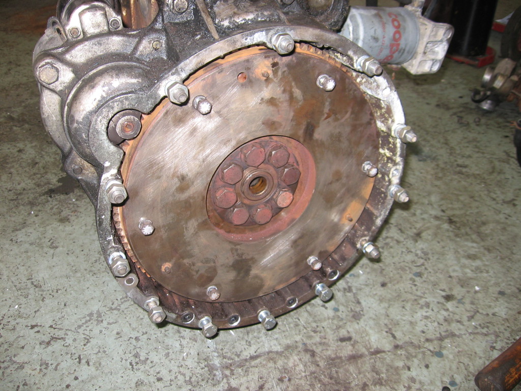
Bellhousing preparation: the Disco engine will bolt up to the Series bellhousing quite happily, but there are a couple of problems. Firstly at the bottom of the bellhousing a Discovery has four long M10 bolts which go through the flywheel housing and screw into the cast alloy stiffening plate between the engine block and sump pan. I suspect these bolts are quite important in reducing vibration and preventing undue stress at the join between engine and gearbox, as well as preventing the flywheel housing from pulling away from the back of the block and leaking oil. However, the Series bellhousing does not have holes for these four bolts - instead it has holes for three studs, which are not present on the Discovery flywheel housing. There is another stud missing on the right hand side - four studs missing out of a total of twelve. Many people have ignored this problem and simply bolted the Disco motor to the Series bellhousing with no ill effects so far (although it might explain why so many TDi conversions seem to leak oil from the back of the engine). But if you want to do a proper job, I strongly recommend that you do something about these problems.
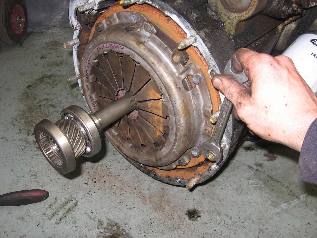
First, remove the flywheel from your Discovery engine, followed by the flywheel housing. There is a stud in the flywheel housing which needs to be removed (see photo below) and there may also be two steel dowels in the rear face of the flywheel housing. These must be removed if present. One of the dowels can be seen next to my thumb in the photo below. To remove studs, simply run two nuts onto the stud, then turn them against each other to lock them together. If you turn the innermost nut anti-clockwise with a spanner, the stud should now unscrew from the flywheel housing. The dowels usually pull out quite easily with Mole grips. If they are really stuck you can drill them or grind them flat.
Now you need to counterbore the four holes in the bottom of the flywheel housing to take M10 x 80 Allen bolts, then drill and tap the housing M10 to take the four extra studs. The housing has blind holes in exactly the right places for the four studs. This works equally well for Series and Defender vehicles. The photo below shows the housing modified and fitted to the engine with all studs and bolts in place. Note the four Allen bolts at the bottom of the flywheel housing, which go through the housing and into the block stiffener:
To do this properly you really need a pillar drill, an M10 counterbore and an M10 x1.5 thread cutting tap, as well as the Allen bolts which are hard to buy in small quantities. Also you need to fit a new oil seal, and these can be difficult to fit without distorting them unless you have the right tools. For this reason I can now modify your flywheel housing for you. This comes with the four holes counterbored for the long through bolts, extra stud holes drilled and tapped, all bolts, studs, nuts and lockwashers as in the photo immediately above and a new oil seal carefully fitted using a hydraulic press. Price is £65 (including postage) - simply send your flywheel housing along with your return address and a cheque to Glencoyne Engineering, Unit 10 Heath Road Industrial Estate, Banham, Norfolk NR16 2HS, or let me have your email address and I can send you an invoice and bank details. I can usually turn these round in a couple of days.
Refit the modified flywheel housing to the block with a new gasket ERR1440 if required. (Some early TDis used RTV sealant instead of a gasket). You need to be very careful when fitting it, to avoid damaging the new crank seal. The seal has a plastic sleeve inside it which fits over the end of the crankshaft to protect the lip of the seal. Position the flywheel housing on the two studs, making sure the plastic sleeve is securely located over the crankshaft end, then use tighten the housing-to-block bolts slowly and progressively. Make sure the housing is pulled onto the block squarely and that the sleeve does not slip out of position before the seal is safely in position over the end of the crankshaft. Discard the plastic sleeve after fitting. Now fit the flywheel - use Loctite on the bolt threads and do them up to the specified torque.
Next you can fit the clutch after you have checked that the spigot bush is in good condition (replace if worn or loose in the end of the crank). The 200 TDi flywheel will take the 9.5 inch Series clutch plate, with either the Series 2A (diesel) or Series 3 cover, so if the clutch from your old engine is in good condition you can probably swap it straight over. If you are replacing a petrol engine in a Series 2/2A with the 9 inch coil spring clutch, you will need to upgrade to the 9.5 inch clutch. Make sure the clutch plate is perfectly centred - I use an old gearbox input shaft for this job - worth paying a few quid for a scrap Series gearbox just to get this bit. I sell OEM quality clutches for either Series 2/2A or Series 3 applications via my web shop.
Last job before fitting the engine is to sort out some engine mounts. Assuming you have just removed a standard 2 1/4 petrol or diesel engine from your Landie, simply unbolt the mounts from this and bolt them to the 200 TDi block. On the nearside there are two sets of threaded holes - use the front set. Now you can fit the new engine (as per the workshop manual) using Series engine mounting rubbers, or Defender 200TDi items. Vibration can be a major problem with the 200TDi engine - it is a rough old thing, and cheap 'pattern' engine mounts do it no favours at all. After much experimentation I now use high quality OEM Defender mounts, trimmed with an angle grinder to fit the chassis mounting brackets. Again these are available via my web shop - not as cheap as the pattern mounts but you will know where the money has gone.
Plumbing in your new engine will be fairly straightforward, provided you do things in a sensible and methodical fashion. Starting with the alternator, you have several options. You can bolt the Lucas 16ACR alternator (as used on Series 3 Land Rovers) straight onto the 200TDi bracket as shown below, but if you are using your Series alternator, the front plate will need to be rotated to put the adjuster lug in the right place. Next problem is that on the Disco TDi, the alternator is driven off the power steering pump. If you are fitting the engine to a Series vehicle, or a Defender without power steering, you will find that the standard alternator pulley does not line up with the crank pulley. To get round this you can use a military type double pulley as in the photo below. Alternatively you can use the Disco 200TDi alternator with a long nose pulley from a VW Golf or similar. You need to measure the distance around the pulleys to find out what length fan belt you need. The installation below uses a belt from a series 3 109 V8.
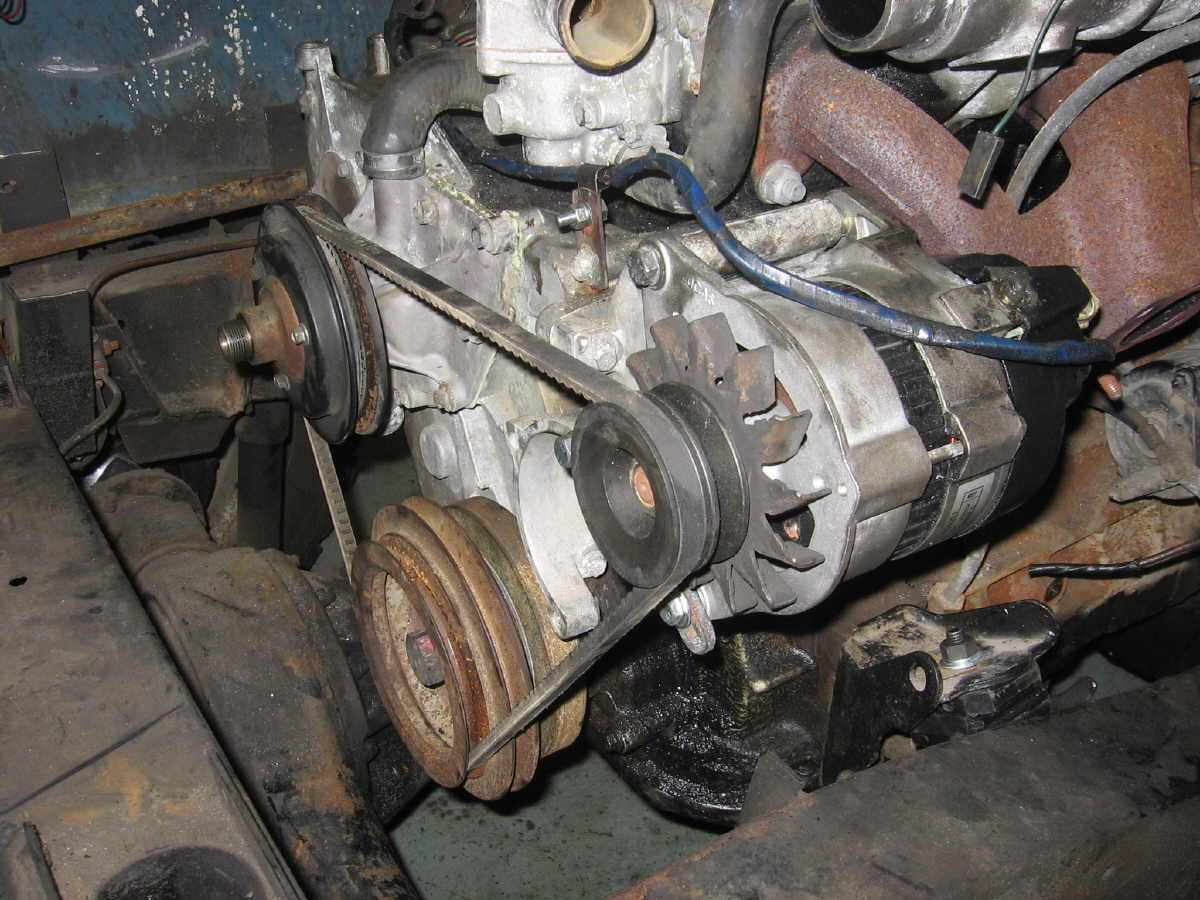
After I had done a few of these I thought there had to be a way to use the Disco alternator without hunting around for obscure VW parts. So I had some heavy duty spacers machined to allow me to fit the Series alternator bracket to the 200TDi engine block as in the photo below. This gives a much neater installation with a shorter belt (actually a standard Defender TDi belt). It also gives a bit more clearance for the air intake hose if you are keeping the turbo. It will work equally well for Series or Defender (non power steering) TDi installations.
The 200TDi alternator will fit the Series mounting bracket, and gives usefully more power (65 amps versus 34), but the front plate will need rotating 120 degrees to put the adjuster lug in the right place. I used to sell the spacers as a kit, but you can now buy CNC machined aluminium spacer blocks on eBay which are a much better solution, although you will have to source your own mounting bolts
You can now go on to wire up the rest of the electrics. How you do this will depend on the year and model of vehicle, and if I were to provide detailed instructions for every variant of Series Land Rover I would never find the time to get this page finished. In all cases you will need to relocate the battery under the passenger seat and make up a clamp to hold it securely in place. If you have the positive battery lead from the donor Discovery, this should comfortably reach from the starter solenoid to the battery in its new location. The battery negative lead should be bolted direct to the engine/gearbox assembly, with an earth strap from the engine/gearbox to the chassis. All the fixing points for this leads need to be nice and clean, and securely bolted. Series 2/2A Landies had a battery tray under the passenger seat which should take an 069 battery, but if you do not have the battery tray, you will find an 075 will fit in the front LH corner of the underseat tool locker and will have plenty enough power to fire up the engine.
The alternator can be connected as per the Series 3 diesel wiring diagram (using the original wiring if you are converting a Series 3). The starter solenoid wire (red/white) should connect straight to the solenoid on a diesel vehicle, but for petrol vehicles with a separate starter solenoid you will have to extend this wire. For pre 1967 vehicles with a starter button, you can still use this to actuate the starter solenoid - just connect a positive supply to one side, and connect the other side to the spade terminal on the starter solenoid.
Being a fairly modern diesel, the 200TDi has an electrically operated stop solenoid, rather than a cable operated system. If converting a petrol vehicle, simply extend the + wire which previously fed the ignition coil, and connect it to the stop solenoid. If you are converting a diesel Land Rover with series 3 combined starter and glowplug switch, you will find that when the starter is operated it disconnects all the switched electrical circuits. So you will need a 4 pin relay, which when actuated connects the glowplug feed to the stop solenoid (glowplugs are powered while the starter is operating). The actuating feed for this relay should be from the red/white wire to the starter solenoid. You will also need to identify a live switched feed (the + feed to the brake light switch is ideal) and connect this to the stop solenoid also. Alternatively you can swap the ignition switch for one from a Defender 2.5 NA or TD (which gives you a terminal to power the glow plugs) or a petrol type ignition switch (if you are using the TDi glowplug relay as below).
Finally on the electrical front, you need to do something about the glowplugs. Easy if you are converting a diesel as you already have a switch and wiring. For a petrol vehicle, try to get hold of the glowplug relay and wiring from the donor Discovery. Connection is very simple. Of the two heavy leads, the brown goes to the battery connection on the back of the starter solenoid, the black/yellow wire connects to the glowplugs. Of the thinner wires, black is earth, white connects to the ignition feed (also white), red and white connects to the starter solenoid (also red and white) and the brown and white (or sometimes yellow and black) wire is the earth return from the cold start warning light, the other side of which needs to be connected to a switched live feed (such as the ignition feed). Now when you switch on the ignition the yellow warning light should come on for a few seconds (to show the heater plugs are working) then go out. You will find that, except in very cold weather, this engine should fire up easily without any need for glowplugs, but it makes sense to wire them up just in case they are needed.
On the next page we will look at fuelling, cooling and exhaust systems. Click here to continue.
DIFAQ - frequently asked questions - click here
Web shop - 200Di/TDi conversion bits - click here